Travelling Wave Event Location with Optical Sensors
Installation
Practical, simple, safe, and rapid deployment
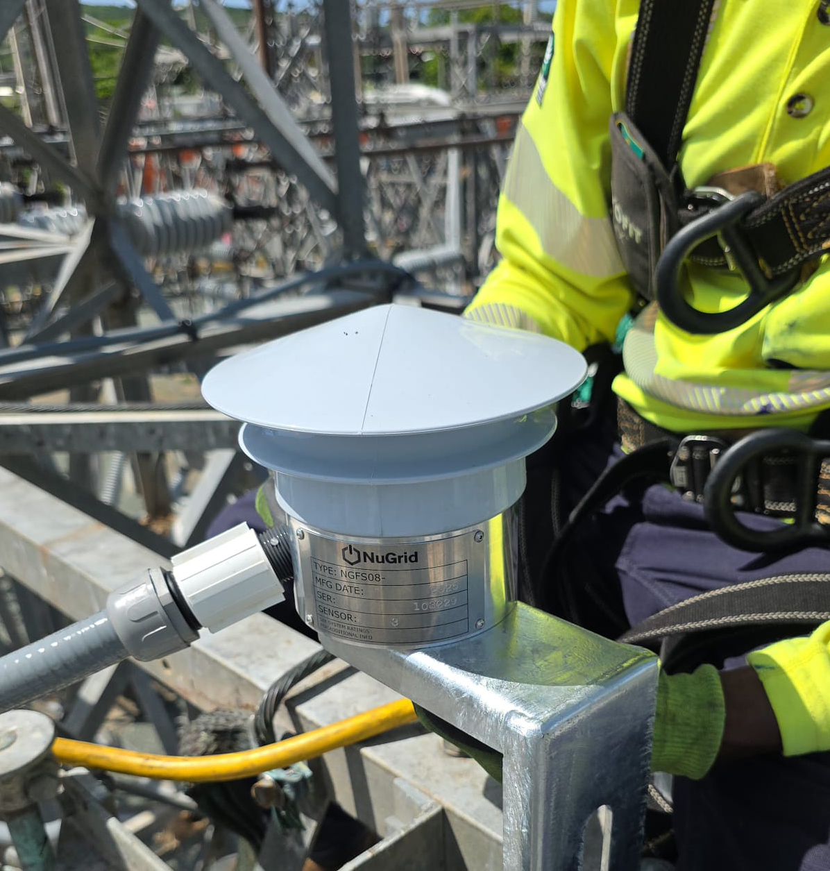
Optical sensors installed at ground potential
Safe design - no electronics or conductive wires at/to the high voltage
Electric field (voltage) based approach - minimizes need for sensors (1 sensor system per substation bus) and can also be integrated with magnetic field sensors
High sampling rate at 1 MHz
User selectable triggers to detect events
1 microsecond GPS time tagging accuracy allows fault location within 500 feet (150 m) and enables disturbance propagation monitoring (stability analysis) across the grid
Low-cost installation - no possible interaction with relays, instrument transformers or other HV equipment

NGFS sensors can be mounted on a variety of structures

Operation
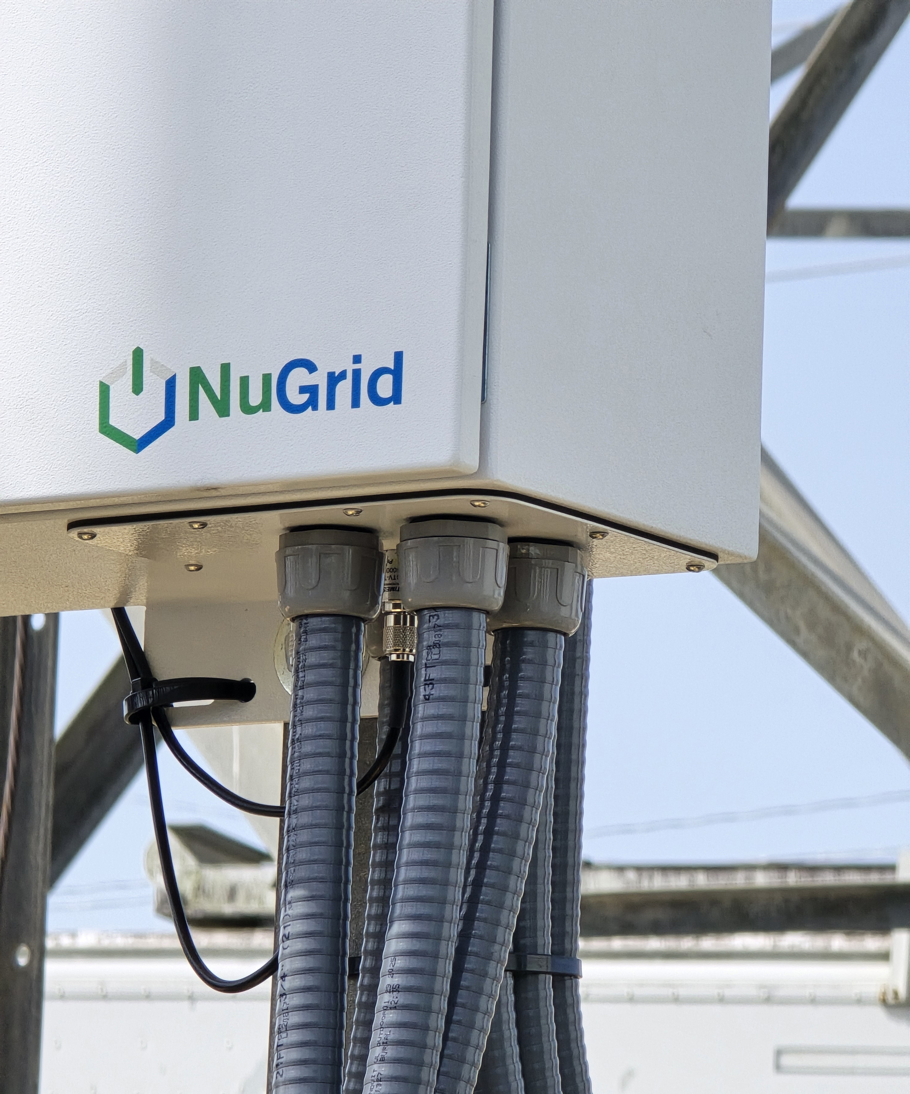
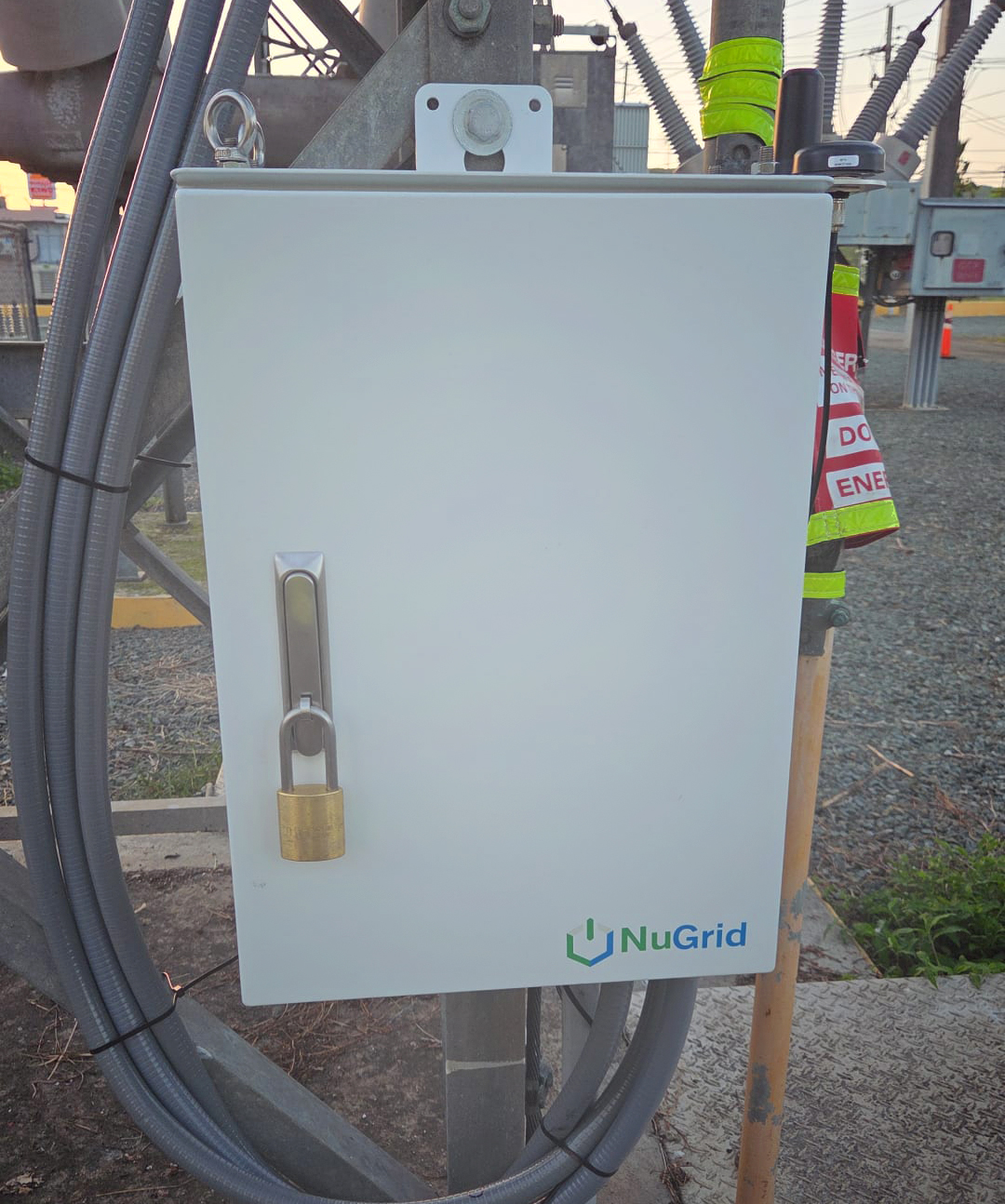
Signal processing unit at ground potential
Connects via fiber (all dielectric) to the passive optical sensors
Events trigger waveform capture at one or more measurement nodes
High resolution events are sent wirelessly (or via fiber) to data repository
Automatic notification to user (via email or text) of event location and attributes
Event Analysis Software
Waveform visualization
Events are easily sorted and uploaded from data repository
Triggered events from multiple sensors can be compared
Single-ended or double-ended TW event location
Fault location accuracy <500 feet
Mapping module provides latitude and longitude with map display pin
Relay/breaker/protection performance assessment with microsecond resolution
Incipient faults can be targeted for mitigation (e.g., occasional arcing in defective polluted insulator etc.)
Fault history visualization and records support asset management prioritization


